Некоммерческое акционерное общество
АЛМАТИНСКИЙ УНИВЕРСИТЕТ ЭНЕРГЕТИКИ И
СВЯЗИ
Кафедра
Иностранные языки
АНГЛИЙСКИЙ ЯЗЫК
(профессиональный)
Методические указания для магистрантов по специальности
6М071800- Электроэнергетика
Алматы, 2013
СОСТАВИТЕЛЬ: Л.Д. Сергеева. Английский язык (профессиональный). Методические указания для магистрантов по специальности 6М071800 - Электроэнергетика – Алматы: АУЭС, 2013. – 64с.
Данные методические указания предназначены для магистрантов специальности 6М071800 – Электроэнергетика с целью формирования профессиональной компетенции будущих специалистов. Темы для методического указания выбраны согласно программе для магистратуры массачусетского технологического университета (MIT) специальности Электроэнергетика.
Рецензент: канд.филолог.наук, доцент АУЭС Козлов В.С.
Печатается по плану издания некоммерческого акционерного общества «Алматинский университет энергетики и связи» на 2013 г.
© НАО «Алматинский университет энергетики и связи», 2014г.
Unit 1
Power factor correction
Text 1
How can you economize?
A great deal of money is spent annually to achieve savings in production methods, improved plant efficiency and optimum lighting arrangements; essential in the highly competitive world of industry today. However, poorly managed energy supplies result in unnecessary and avoidable wastage. Power factor correction is the established method of reducing electricity costs in industry and commerce.
You can eliminate waste in electricity consumption by improving your power factor and saving up to 20% on your electricity costs.
This could also help you to increase your output without the need to install new cables or extra supply capacity.
What is Power Factor Correction?
Most loads on an electrical distribution system fall into one of three categories: resistive, inductive or capacitive. In your own plant, the most common is likely to be inductive. Typical examples of this include transformers, fluorescent lighting and AC induction motors. Most inductive loads use a conductive coil winding to produce an electromagnetic field, allowing the motor to function.
All inductive loads require two kinds of power to operate:
1) Active power (kwatts) - to produce the motive force.
2) Reactive power (KVAR) - to energize the magnetic field.
The operating power from the distribution system is composed of both active (working) and reactive (non-working) elements. The active power does useful work in driving the motor whereas the reactive power only provides the magnetic field. The bad news is that you are charged for both!
The objective, therefore, should be to reduce the reactive power drawn from the supply by improving the power factor.
If an AC motor were 100% efficient it would consume only active power but, since most motors are only 75% to 80% efficient, they operate at a low power factor. This means poor energy and cost efficiency because the Regional Electricity Companies charge you at penalty rates for poor power factor.
By installing capacitors to improve your power factor you could SAVE MONEY on your electricity bill.
Additional potential benefits include:
1) Reduction of heating losses in transformers and distribution equipment.
2) Longer plant life.
3) Stabilized voltage levels.
4) Increase in capacity of your existing system and equipment.
5) Improved profitability.
1.1 Match the collocations with Russian equivalents:
a) plant efficiency, lighting arrangements, energy supplies, avoidable wastage, power factor, power factor correction, reducing electricity costs, electricity consumption, eliminate waste, increase output, electrical distribution system, conductive coil winding, inductive loads, penalty rates, heating losses, distribution equipment;
b) потребление электричества, проводящая обмотка катушки, коэффициент мощности, распределительное оборудование, штрафные ставки, энергоснабжение, устранить потери, избегаемые потери, индуктивные нагрузки, механизмы освещения, увеличить выходную мощность, электрическая распределительная система, потери тепла, снижение цен на электричество, увеличение коэффициента мощности, производительность электростанции.
1.2 Fill in the gaps with following words:
|
improving motor reducing low eliminate efficiency inductive |
1) A great deal of money is spent annually to achieve savings in production methods, improved plant ___ and optimum lighting arrangements.
2) Power factor correction is the established method of ___ electricity costs in industry and commerce.
3) You can ___ waste in electricity consumption by improving your power factor and saving up to 20% on your electricity costs.
4) Most loads on an electrical distribution system fall into one of three categories: resistive, ___ or capacitive.
5) The active power does useful work in driving the ___ whereas the reactive power only provides the magnetic field.
6) The objective, therefore, should be to reduce the reactive power drawn from the supply by ___ the power factor.
7) If an AC motor were 100% efficient it would consume only active power but, since most motors are only 75% to 80% efficient, they operate at a ___ power factor.
1.3 Match two parts of the sentence:
|
1 A great deal of money is spent annually |
a) one of three categories: resistive, inductive or capacitive. |
|
2 Poorly managed energy supplies result in |
b) useful work in driving the motor. |
|
3 Power factor correction is the established method of reducing electricity costs in industry and commerce. |
c) only provides the magnetic field. |
|
4 Most loads on an electrical distribution system fall into |
d) to reduce the reactive power drawn from the supply by improving the power factor. |
|
5 Most inductive loads use a conductive coil winding |
e) to achieve savings in production methods, improved plant efficiency and optimum lighting arrangements. |
|
6 The operating power from the distribution system is composed of |
f) to produce an electromagnetic field, allowing the motor to function. |
|
7 The active power does |
g) since most motors are only 75% to 80% efficient, they operate at a low power factor. |
|
8 The reactive power |
h) reducing electricity costs in industry and commerce. |
|
9 The objective, therefore, should be |
i) both active (working) and reactive (non-working) elements. |
|
10 If an AC motor were 100% efficient it would consume only active power but, |
j) unnecessary and avoidable wastage. |
1.4 Answer the questions:
1) What is annually a great deal of money spent to?
2) What is power factor correction?
3) How can you eliminate waste in electricity consumption?
4) What are three categories most loads on an electrical distribution system fall into?
5) What do the most inductive loads use to produce an electromagnetic field?
6) What kinds of power do all inductive loads require to operate?
7) What difference is between active (working) and reactive (non-working) elements?
8) Why can you be charged at penalty rates by Regional Electricity Companies?
Text 2
Power Factor Correction
The power factor of an AC electric power system is defined as the ratio of the real power flowing to the load to the apparent power in the circuit, and is a dimensionless number between 0 and 1 (frequently expressed as a percentage, e.g. 0.5 pf = 50% pf). Real power is the capacity of the circuit for performing work in a particular time. Apparent power is the product of the current and voltage of the circuit. Due to energy stored in the load and returned to the source, or due to a non-linear load that distorts the wave shape of the current drawn from the source, the apparent power will be greater than the real power.
In an electric power system, a load with a low power factor draws more current than a load with a high power factor for the same amount of useful power transferred. The higher currents increase the energy lost in the distribution system, and require larger wires and other equipment. Because of the costs of larger equipment and wasted energy, electrical utilities will usually charge a higher cost to industrial or commercial customers where there is a low power factor.
Linear loads with low power factor (such as induction motors) can be corrected with a passive network of capacitors or inductors. Non-linear loads, such as rectifiers, distort the current drawn from the system. In such cases, active or passive power factor correction may be used to counteract the distortion and raise the power factor. The devices for correction of the power factor may be at a central substation, spread out over a distribution system, or built into power-consuming equipment.
1.5 Match the collocations with Russian equivalents:
a) power factor, ratio, apparent power, spike, to eliminate, dimensionless, to distort, rectifier, substation.
b) искажать, отношение, устранять, подстанция, полная мощность, в относительных единицах, пик, коэффициент мощности, выпрямитель.
1.6 Match two parts of the sentence:
|
a) The power factor of an AC electric power system is defined |
1) at a central substation, spread out over a distribution system, or built into power-consuming equipment. |
|
b) Real power is the capacity of the circuit |
2) electrical utilities will usually charge a higher cost to industrial or commercial customers where there is a low power factor. |
|
c) In an electric power system, a load with a low power factor draws more current than |
3) for performing work in a particular time. |
|
d) Because of the costs of larger equipment and wasted energy |
4) distort the current drawn from the system. |
|
e) Linear loads with low power factor (such as induction motors) can be corrected with |
5) a load with a high power factor for the same amount of useful power transferred. |
|
f) Non-linear loads, such as rectifiers |
6) as the ratio of the real power flowing to the load to the apparent power in the circuit. |
|
g) The devices for correction of the power factor may be |
7) a passive network of capacitors or inductors. |
1.7 Answer the questions:
1) How is the power factor of an AC electric power system defined?
2) What is real power?
3) What is apparent power?
4) Why will be power be greater than the real power?
5) Why does a load with a low power factor draw more current than a load with a high power factor for the same amount of useful power transferred?
6) How can linear loads with low power factor (such as induction motors) be corrected?
7) When may active or passive power factor correction be used?
8) Where may the devices for correction of the power factor be?
Text 3
Power Factor Correction, how does it work?
Power Factor correction is applied to circuits which include induction motors as a means of reducing the inductive component of the current and thereby reduce the losses in the supply. There should be no effect on the operation of the motor itself.
An induction motor draws current from the supply that is made up of resistive components and inductive components. The resistive components are:
1) load current;
2) loss current and the inductive;
3) leakage reactance;
4) magnetizing current.
The current due to the leakage reactance is dependent on the total current drawn by the motor, but the magnetizing current is independent of the load on the motor. The magnetizing current wilt typically is between 20% and 60% of the rated full load current of the motor. The magnetizing current is the current that establishes the flux in the iron and is very necessary if the motor is going to operate. The magnetizing current does not actually contribute to the actual work output of the motor. It is the catalyst that allows the motor to work property. The magnetizing current and the leakage reactance can be considered passenger components of current that wit (not affect the power drawn by the motor, but wilt contribute to the power dissipated in the supply and distribution system). Take for example a motor with a current draw of 100 Amps and a power factor of 0.75. The resistive component of the current is 75 Amps and this is what the KWh meter measures. The higher current will result in an increase in the distribution losses of (100 x 100) / (75 x 75) = 1.777 or a 78% increase in the supply losses.
In the interest of reducing the losses in the distribution system, power factor correction is added to neutralize a portion of the magnetizing current of the motor. Typically, the corrected power factor will be 0.92 - 0.95. Some power retailers offer incentives for operating with a power factor of better than 0.9, while others penalize consumers with a poor power factor. There are many ways that this is metered, but the net result is that in order to reduce wasted energy in the distribution system, the consumer will be encouraged to apply power factor correction.
Power factor correction is achieved by the addition of capacitors in parallel with the connected motor circuits and can be applied at the starter, or applied at the switchboard or distribution panel. The resulting capacitive current is leading current and is used to cancel the [aging inductive current flowing from the supply.
Capacitors connected at each starter and controlled by each starter is known as "Static Power Factor Correction" white capacitors connected at a distribution board and controlled independently from the individual starters is known as "Bulk Correction".
Bulk Correction. The Power factor of the total current supplied to the distribution board is monitored by a controller which then switches capacitor banks I a fashion to maintain a power factor better than a preset limit. (Typically 0.95) Ideally, the power factor should be as close to unity as possible. There is no problem with bulk correction operating at unity.
1.8 Answer the questions:
1) In which circuits is Power Factor correction applied?
2) What are the resistive components of the supply?
3) Why is the current dependent on?
4) What is the magnetizing current?
5) Does the magnetizing current actually contribute to the actual work output of the motor?
6) What are passenger components of current?
7) What is typical corrected power factor?
8) What is the net result for operating with a power factor?
9) How is Power factor correction achieved?
10) What is leading current?
11) What is "Static Power Factor Correction"?
12) What is ideal power factor?
1.9 Read the text 3 and write annotation.
How to Write Annotations
An annotation is a brief summary of a book, article, or other publication. An abstract is also a summary, but there is a difference between the two. An abstract is simply a summary of a work, whereas the purpose of an annotation is to describe the work in such a way that the reader can decide whether or not to read the work itself. An annotated bibliography helps the reader understand the particular usefulness of each item. The ideal annotated bibliography shows the relationships among individual items and may compare their strengths or shortcomings.
The following points provide guidance for writing annotations. As appropriate each of these issues might be assessed and commented on in the annotation.
1. Qualifications of the author, unless very well known.
2. The scope and main purpose of the publication (e.g., book, article, web site).
3. The intended audience and level of reading difficulty.
4. The author's bias or assumptions, upon which the work's rationale rests.
5. The method of obtaining data or doing research.
6. The author's conclusions.
7. Comparison with other works on the same subject.
8. Materials appended to the work — e.g., maps, charts, photos, etc.
9. The work's importance or usefulness for the study of a subject.
Not all of these points are necessary for every annotation, and they certainly do not have to be noted in the order listed here, but they at least ought to be kept in mind when writing an annotation.
Useful phrases:
The article deals with …
As the title implies the article describes...
The paper is concerned with…
It is known that…
It should be noted about…
The fact that … is stressed.
A mention should be made about …
It is spoken in detail about…
It is reported that …
The text gives valuable information on…
Much attention is given to…
It is shown that…
The following conclusions are drawn…
The paper looks at recent research dealing with…
The main idea of the article is…
It gives a detailed analysis of…
It draws our attention to…
It is stressed that…
The article is of great help to …
The article is of interest to …
Text 4
Static Correction
As a large proportion of the inductive or tagging current on the supply is due to the magnetizing current of induction motors, it is easy to correct each individual motor by connecting the correction capacitors to the motor starters. With static correction, it is important that the capacitive current is less than the inductive magnetizing current of the induction motor. In many installations employing static power factor correction, the correction capacitors are connected directly in parallel with the motor windings. When the motor is Off Line, the capacitors are also Off Line. When the motor is connected to the supply, the capacitors are also connected providing correction at all times that the motor is connected to the supply. This removes the requirement for any expensive power factor monitoring and control equipment. In this situation, the capacitors remain connected to the motor terminals as the motor slows down. An induction motor, while connected to the supply, is driven by a rotating magnetic field in the stator which induces current into the rotor. When the motor is disconnected from the supply, there is for a period of time, a magnetic field associated with the rotor. As the motor decelerates, it generates voltage out its terminals at a frequency which is related to its speed. The capacitors connected across the motor terminals, form a resonant circuit with the motor inductance. If the motor is critically corrected, (corrected to a power factor of 1.0) the inductive reactance equals the capacitive reactance at the tine frequency and therefore the resonant frequency is equal to the time frequency. If the motor is over corrected, the resonant frequency will be below the line frequency. If the frequency of the voltage generated by the decelerating motor passes through the resonant frequency of the corrected motor, there will be high currents and voltages around the motor/capacitor circuit. This can result in severe damage to the capacitors and motor. It is imperative that motors are never over corrected or critically corrected when static correction is employed.
Static power factor correction should provide capacitive current equal to 80% of the magnetizing current, which is essentially the open shaft current of the motor.
The magnetizing current for induction motors can vary considerably. Typically, magnetizing currents for large two pole machines can be as low as 20% of the rated current of the motor while smatter low speed motors can have a magnetizing current as high as 60% of the rated full load current of the motor. It is not practical to use a "Standard table" for the correction of induction motors giving optimum correction on all motors. Tables result in under correction on most motors but can result in over correction in some cases. Where the open shaft current cannot be measured, and the magnetizing current is not quoted, an approximate level for the maximum correction that can be applied can be calculated from the half load characteristics of the motor. It is dangerous to base correction on the full load characteristics of the motor as in some cases, motors can exhibit a high leakage reactance and correction to 0.95 at full load will result in over correcting under no load, or disconnected conditions.
Static correction is commonly applied by using one contactor to control both the motor and the capacitors. It is better practice to use two contactors, one for the motor and one for the capacitors. Where one contactor is employed, it should be upsized for the capacitive load. The use of a second contactor eliminates the problems of resonance between the motor and the capacitors.
Static Power factor correction must not be used when the motor is controlled by a variable speed drive or inverter.
Static Power Factor correction capacitors must not be connected to the output of a solid state soft starter. When a solid state soft starter is used, the capacitors must be controlled by a separate contactor, and switched in when the soft starter output voltage has reached line voltage. Many soft starters provide a "top of ramp" or "bypass contactor control" which can be used to control the power factor correction capacitors.
1.10 Answer the questions:
1) How can each individual motor be corrected?
2) What is it important with static correction?
3) How are the correction capacitors connected in many installations employing static power factor correction?
4) What is the connection between the motor and the capacitors?
5) What does the inductive reactance equal if the motor is critically corrected (corrected to a power factor of 1.0)?
6) What will the resonant frequency be if the motor is over corrected?
7) What is difference in magnetizing currents for large two pole machines and smatter low speed motors?
8) Is it practical to use a "Standard table" for the correction of induction motors? Why?
9) How can an approximate level for the maximum correction that can be applied be calculated where the open shaft current cannot be measured, and the magnetizing current is not quoted?
10) When is static correction commonly applied?
11) When must not static Power factor correction be used?
12) Why must not Static Power Factor correction capacitors be connected to the output of a solid state soft starter?
1.11 What is the meaning of the following terms?
tagging current, correction capacitors, motor starters, static correction, capacitive current, motor windings, Off Line, control equipment, slows down, rotating magnetic field, motor decelerates, motor terminals, a resonant circuit, motor inductance, capacitive reactance, tine frequency, resonant frequency, over corrected, critically corrected, open shaft current, rated current, toad current, leakage reactance, eliminates the problems, output, a solid state soft starter, top of ramp, bypass contactor control.
1.12 Read the text and find the ending of the following sentences in it. Translate them into Russian.
1 As a large proportion of the inductive or tagging current on the supply is due to the magnetizing current of induction motors,…
2 With static correction, it is important that …
3 In many installations employing static power factor correction,…
4 When the motor is Off Line…
5 When the motor is connected to the supply,…
6 An induction motor, white connected to the supply…
7 If the motor is critically corrected…
8 If the motor is over corrected,…
9 It is imperative that motors are never …
10 Static power factor correction should provide capacitive current equal to…
11 Typically, magnetizing currents for large two pole machines can be …
12 Where the open shaft current cannot be measured, and the magnetizing current is not quoted…
13 Static correction is commonly applied by using one contactor to control…
14 Static Power factor correction must not be used when …
15 Static Power Factor correction capacitors must not be connected to…
Text 5
Capacitor selection
Static Power factor correction must neutralize no more than 80% of the magnetizing current of the motor. If the correction is too high, there is a high probability of over correction which can result in equipment failure with severe damage to the motor and capacitors. Unfortunately, the magnetizing current of induction motors varies considerably between different motor designs. The magnetizing current is almost always higher than 20% of the rated full load current of the motor, but can be as high as 60% of the rated current of the motor. Most power factor correction is too tight due to the selection based on tables which have been published by a number of sources. These tables assume the lowest magnetizing current and quote capacitors for this current. In practice, this can mean that the correction is often less than half the value that it should be, and the consumer is unnecessarily penalized. Power factor correction must be correctly selected based on the actual motor being corrected. The Bus bar software provides two methods of calculating the correct value of KVAR correction to apply to a motor. The first method requires the magnetizing current of the motor. Where this figure is available, then this is the preferred method. Where the magnetizing current is not available, the second method is employed and is based on the half Load power factor and efficiency of that motor. These figures are available from the motor data sheets.
For example: Motor A is a 200 KW 6 pole motor with a magnetizing current of 124A. From tables, the correction applied would be 37KVAR. From the calculations, this would require a correction of 68.7 KVAR.
Motor B is a 375KW 2 pole motor with a half toad efficiency of 93.9% and a half toad power factor of 0.805, the correction recommended by the tables is 44 KVAR white the calculations reveal that the correction should be 81.3KVAR.
1.13 Read the text and find the ending of the following sentences in it. Translate them into Russian.
1 Static Power factor correction must neutralize no more than …
2 If the correction is too high …
3 Unfortunately, the magnetizing current of induction motors varies considerably…
4 Most power factor correction is too tight due to …
5 These tables assume …
6 In practice, this can mean that the correction is often …
7 Power factor correction must be correctly selected based on …
8 The Bus bar software provides …
9 The first method requires …
10 Where the magnetizing current is not available …
1.14 Read the text and match abbreviations KV, KW, KVA, KWAR with their definitions:
1) ___ kilo
volts, which is a measure of potential difference (volts/1000).
2) ___ kilo (thousands of) volts times amperes, reactive, which is a
measure of the rate of energy that is sloshing back and forth, twice a cycle,
between an AC source and a reactive (capacitive or inductive) load. The phase
difference between the voltage wave and the current wave components used for
this measure is + or - 90 degrees.
3) ___ kilo (thousands of) volts times amperes. The product of the RMS volts across a load or source times the RMS current passing through the load or source divided by 1000. If the load has a reactive component, this is the square root of the sum of the squares of the KW and the KVAR. But knowing just the KVA, you do not know what part is KW and what part is KVAR. But it is easy to measure with a volt and amp meter. The phase angle between the voltage wave and the current wave is somewhere between +- 90 degrees.
4) ___ kilowatts. This is the RMS volts times the RMS current divided by 1000, where the voltage wave and the current wave are in phase (zero degrees phase shift. Or, for any voltage and current waveforms and phases, the average of the instantaneous product of voltage and current, divided by 1000. It is the measure of unidirectional rate of energy transfer from source to load (if positive). If the load has a reactive component (voltage and current not in phase), only the components of the voltage and current waves that are in phase are used to make this measurement.
1.15 Read the text and try to remember what the numbers mean:
80%, 20%, 60%, 200 KW, 124A, 37KVAR, 68.7 KVAR, 375KW, 44 KVAR, 81.3KVAR.
Text 6
Why Use Capacitors?
Most electrical systems service a wide variety of inductive loads including motors, transformers, and fluorescent lighting. One characteristic of inductive loads is that they utilize a winding in order to operate. When energized, this winding produces an electromagnetic field which enables the motor or transformer to function. The electrical power required to energize this winding is called reactive power. The other characteristic of inductive loads is that in addition to reactive power, they also require active power to actually perform the work. Without capacitors, the local power utility must provide both reactive and active power. The more reactive power required setting up the magnetic field, the more power (KVA) the utility must supply. Capacitors act as reactive current generators. With capacitors on line, then, this not only frees the utility from having to supply reactive power, but also frees the distribution system to carry more active power (KW).
Capacitors save You Money!
Power factor ratings are a measurement of how effectively a plant uses electrical power. The higher the ratings the more effective the electrical power is being used and vice versa. Power factor correction capacitors can save you money in several ways!
As more and more utility companies are assessing penalty charges for low power factors, power factor correction capacitors eliminate these costly penalties.
Secondly, since all systems waste a certain amount of power through line losses in conductors, the reduction in current draw which results from the addition of capacitors reduces losses significantly, thus reducing the power bill. Finally, the addition of capacitors may prove a very favorable alternative to expanding the distribution system when additional capacity is required as less electrical power can be utilized more effectively. ASEA Capacitors offer numerous technical advantages.
Self-Healing
"Self -healing" is a characteristic which is unique to metalized-film capacitors. All capacitors normally experience insulation breakdown as a result of the accumulated effect of temperature, voltage stress, impurities in the insulating medium, etc. When this happens in a non-metalized design, the electrodes are short-circuited and the capacitor ceases its production of reactive power. In an ASEA metalized-film unit, however, these individual insulation breakdowns do not mean the shutdown of the capacitor. The faults self-heal themselves and the capacitor continues operation.
Dry Construction
ASEA low voltage capacitors contain no free liquids and are filled with a unique non-flammable granular material called vermiculite. Environmental and personnel concerns associated with leakage or flammability of conventional oil-filled units are eliminated; and KVAR for KVAR, vermiculite filled units weigh 30% to 60% less than their oil-filled counterparts.
Thanks to the highly efficient polypropylene dielectric used in ASEA capacitors, total losses, including those across discharge resistors, are less than 0.5 watts/KVAR which is much less than conventional designs.
The unique IPE Sequential Protection System provides the ultimate system for safety and protection including:
1) Dry, self-healing design.
2) IPE (internally protected elements).
3) Dry, nonflammable vermiculite filler.
At the end of the element's life, the dielectric deteriorates so that self-healing becomes somewhat a continuous process progressing outward from the middle of the element. Every element in an ASEA capacitor is provided with a non-self -healing outer winding to reliably and selectively disconnect the element at the end of its life.
1.16 Answer the questions:
1 What does most electrical systems service?
2 What is one characteristic of inductive loads?
3 What is reactive power?
4 What is the other characteristic of inductive loads?
5 What are power factor ratings?
6 What are 3 advantages of factor correction capacitors?
7 What is unique characteristic of metalized-film capacitors?
8 Why non-flammable granular material called vermiculite is unique?
9 What does IPE Sequential Protection System provide?
1.17 Match the collocations with Russian equivalents:
a) inductive load, capacitor, utilize a winding, power factor ratings, vice versa, utility companies, are assessing, penalty charges, metalized-film capacitor, insulation breakdown, accumulated effect of temperature, impurities in the insulating medium, short-circuited, capacitor ceases, shutdown of the capacitor, faults self-heal themselves, non-flammable granular material, leakage or flammability of conventional oil-filled units;
b)оценки коэффициента мощности, короткое замыкание, металлизированный пленочный конденсатор, отключение конденсатора, коммунальные предприятия, наоборот, накопленное воздействие температуры, негорючий гранулированный материал, штрафы, конденсатор прекращает, оценивают, примеси в изолирующей среде, утечка или воспламеняемость обычных масляных блоков, неисправности самоисправляются, конденсатор, использовать обмотку, индуктивная нагрузка, пробой изоляции.
1.18 Read the text and find the ending of the following sentences in it. Translate them into Russian.
1 Most electrical systems service a wide variety of …
2 One characteristic of inductive loads is …
3 The other characteristic of inductive loads is …
4 Capacitors act as …
5 Power factor ratings are …
6 As more and more utility companies are assessing penalty charges for low power factors, …
7 Secondly, since all systems waste a certain amount of power through line losses in conductors, …
8 All capacitors normally experience insulation breakdown as a result of …
9 In an ASEA metalized-film unit, however, these individual insulation breakdowns do not mean …
10 ASEA low voltage capacitors contain no free liquids and are …
11 Environmental and personnel concerns associated with …
12 Thanks to the highly efficient polypropylene dielectric used in ASEA capacitors, …
Unit 2
Polуphase power system
Text 7
Polуphase power system
One voltage cycle of a three-phase system
A polyphase system is a means of distributing alternating-current electrical power. Polyphase systems have three or more energized electrical conductors carrying alternating currents with a definite time offset between the voltage waves in each conductor. Polyphase systems are particularly useful for transmitting power to electric motors. The most common example is the three-phase power system used for industrial applications and for power transmission. The most obvious advantage of three-phase power transmission using three wires, as compared to single-phase power transmission over two wires, is that the power transmitted in the three-phase system is the voltage multiplied by the current in each wire times the square root of three (approximately 1.73). The power transmitted by the single-phase system is simply the voltage multiplied by the current. Thus the three-phase system transmits 73% more power but uses only 50% more wire.
Phases
In the very early days of commercial electric power, some installations used two-phase four-wire systems for motors. The chief advantage of these was that the winding configuration was the same as for a single-phase capacitor-start motor and, by using a four-wire system, conceptually the phases were independent and easy to analyze with mathematical tools available at the time.
Two-phase systems can also be implemented using three wires (two "hot" plus a common neutral). However this introduces asymmetry; the voltage drop in the neutral makes the phases not exactly 90 degrees apart.
Two-phase systems have been replaced with three-phase systems. A two-phase supply with 90 degrees between phases can be derived from a three-phase system using a Scott-connected transformer.
A polyphase system must provide a defined direction of phase rotation, so mirror image voltages do not count towards the phase order. A 3-wire system with two phase conductors 180 degrees apart is still only single phase. Such systems are described as split-phase.
Motors
Polyphase power is particularly useful in AC motors, such as the induction motor, where it generates a rotating magnetic field. When a three-or-more-phase supply completes one full cycle, the magnetic field of a two-poles-per-phase motor has rotated through 360° in physical space; motors with more than two poles per phase require more power supply cycles to complete one physical revolution of the magnetic field and so these motors run slower. Nikola Tesla and Michail Dolivo-Dobrovolsky invented the first practical induction motors using a rotating magnetic field - previously all commercial motors were DC, with expensive commutators, high-maintenance brushes and characteristics unsuitable for operation on an alternating current network. Polyphase motors are simple to construct, are self-starting and have little vibration compared with single-phase motors.
Higher phase order
Higher phase numbers than three have been used. A common practice for rectifier installations and in HVDC converters is to provide six phases, with 60 degree phase spacing, to reduce harmonic generation in the AC supply system and to provide smoother direct current. Experimental high-phase-order transmission lines have been built with up to 12 phases. These allow application of Extra High Voltage (EHV) design rules at lower voltages and would permit increased power transfer in the same transmission line corridor width.
2.1 Match the collocations with Russian equivalents:
a) polyphase systems, voltage waves, definite time offset, voltage multiplied, square root, multiplied by, chief advantage, three-phase power transmission, single-phase power transmission, voltage drop, split-phase, a rotating magnetic field;
b) напряжение волны, напряжение умножено, умноженный на, определенный сдвиг во времени, вращающееся магнитное поле, основное преимущество, многофазные системы, квадратный корень, с расщепленной фазой, однофазная передача электроэнергии, падение напряжения, трехфазная передача электроэнергии.
2.2 Match two parts of the sentence:
|
a) A polyphase system is a means of |
1) the three-phase power system used for industrial applications and for power transmission. |
|
b) Polyphase systems have three or more energized electrical conductors |
2) simply the voltage multiplied by the current. |
|
c) Polyphase systems are particularly useful for |
3) so mirror image voltages do not count towards the phase order. |
|
d) The most common example is |
|
|
e) The power transmitted by the single-phase system is |
5) from a three-phase system using a Scott-connected transformer. |
|
f) A two-phase supply with 90 degrees between phases can be derived |
6 transmitting power to electric motors. |
|
g) A polyphase system must provide a defined direction of phase rotation |
7) carrying alternating currents with a definite time offset between the voltage waves in each conductor. |
2.3 Answer the questions:
1) Explain the difference between a balanced polyphase system and an unbalanced polyphase system. What conditions typically cause a polyphase system to become unbalanced? Which type of three-phase system (balanced or unbalanced) is easier to analyze, and why that is so?
2) What is polyphase electric power, and why does it differ from single-phase power?
3) All large electric power generating systems in the world today produce three phase power, rather than single phase power. Explain why this is so, in terms of advantages of distribution and use.
4) How is polyphase (especially three-phase) electric power generated? Single-phase power is easy to understand, but how do we create three-phase AC voltage?
5) Suppose a set of three neon light bulbs were connected to an alternator with three sets of windings labeled A, B, and C:
|
|
The schematic diagram for this alternator/lamp system is as follows:
|
|
If the alternator spins fast enough (clockwise, as shown), the AC voltage induced in its windings will be enough to cause the neon lamps to "blink" (neon bulbs have very fast reaction times and thus cannot maintain a glow for very long without current, unlike incandescent lamps which operate on the principle of a glowing-hot metal filament). Most likely this blinking will be too fast to discern with the naked eye.
However, if we were to video record the blinking and play back the recording at a slow speed, we should be able to see the sequence of light flashes. Determine the apparent "direction" of the lamps' blinking (from right-to-left or from left-to-right), and relate that sequence to the voltage peaks of each alternator coil pair.
6) What is meant by the term phase rotation sequence, in a polyphase electrical system?
7) This is a schematic diagram of a Y-connected three-phase generator (with the rotor winding shown):
How much AC voltage will appear between any two of the lines (VAB, VBC, or VAC) if each stator coil inside the alternator outputs 277 volts? Draw a phasor diagram showing how the phase (winding) and line voltages relate.
8) This is a schematic diagram of a Delta-connected three-phase generator (with the rotor winding shown):
How much AC current will each of the lines (IA, IB, or IC) conduct to a load (not shown) if each stator coil inside the alternator outputs 17 amps of current?
9) Suppose the electrical power supplied to a commercial building is labeled as "208/120 volt". What does this label mean, exactly? Relate this description to a schematic diagram.
10) Suppose you are working on the power wiring inside of a home, and are wondering whether or not the home is supplied with 3-phase or single-phase power. You do not have a voltmeter available to measure voltage, but you do have plenty of light bulbs, switches, wires, and other standard residential wiring components available for use. The two possibilities for this home's power source are shown here, the coils representing secondary windings of the utility power transformer:

An experienced electrician suggests you build the following circuit to test whether or not the home's power is supplied by a 3-phase source or a single-phase source:
The electrician tells you to open and close the switch, and observe the brightness of the light bulbs. This will indicate whether or not the system is 3-phase. Explain how this circuit works. What sort of light bulb behavior would indicate a 3-phase source? What sort of light bulb behavior would indicate a single-phase source?
11) T his Delta-connected three-phase power source provides three different voltage levels: 120 V, 208 V, and 240 V. Determine which points of connection provide these voltages:

12) The line voltage to this three-phase load is 480 volts. How much power (total) is dissipated by the load? How much current is there in each line supplying the load?
One more question: write an equation for calculating power in a balanced, three-phase circuit, given line voltage and line current only.
13) A balanced, three-phase power system has a line voltage of 13.8 kV volts and a line current of 150 amps. How much power is being delivered to the load (assuming a power factor of 1)?
A 13.8 kV single-phase system could be designed to provide the same amount of power to a load, but it would require heavier-gauge (more expensive!) conductors. Determine the extra percentage of expense in wire cost (based on the weight of the wires) resulting from the use of single-phase instead of three-phase.
14) Calculate the full-load line current for a three-phase motor, given a horsepower rating of 150 HP, an efficiency of 93%, and a line voltage of 480 volts. Assume a power factor of 0.90 for full-load conditions.
Text 8
Symmetrical components
In electrical engineering, the method of symmetrical components is used to simplify analysis of unbalanced three phase power systems under both normal and abnormal conditions.
In 1918 Charles Legeyt Fortescue presented a paper which demonstrated that any set of N unbalanced phasors (that is, any such polyphase signal) could be expressed as the sum of N symmetrical sets of balanced phasors, for values of N that are prime. Only a single frequency component is represented by the phasors.
In a three-phase system, one set of phasors has the same phase sequence as the system under study (positive sequence; say ABC), the second set has the reverse phase sequence (negative sequence; ACB), and in the third set the phasors A, B and C are in phase with each other (zero sequence). Essentially, this method converts three unbalanced phases into three independent sources, which makes asymmetric fault analysis more tractable.
By expanding a one-line diagram to show the positive sequence, negative sequence and zero sequence impedances of generators, transformers and other devices including overhead lines and cables, analysis of such unbalanced conditions as a single line to ground short-circuit fault is greatly simplified. The technique can also be extended to higher order phase systems.
Physically, in a three phase winding a positive sequence set of currents produces a normal rotating field, a negative sequence set produces a field with the opposite rotation, and the zero sequence set produces a field that oscillates but does not rotate between phase windings. Since these effects can be detected physically with sequence filters, the mathematical tool became the basis for the design of protective relays, which used negative-sequence voltages and currents as a reliable indicator of fault conditions. Such relays may be used to trip circuit breakers or take other steps to protect electrical systems.
The analytical technique was adopted and advanced by engineers at General Electric and Westinghouse and after World War II it was an accepted method for asymmetric fault analysis.
2.4 Answer the questions:
1) Where is the method of symmetrical components used?
2) What did Charles Legeyt Fortescue present in 1918?
3) What are the functions of each set of phasors in a three-phase system?
4) How can you analyze unbalanced conditions as a single line to ground short-circuit fault?
5) What kinds of fields are produced in a three phase winding?
6) Whom was the analytical technique adopted and advanced by?
2.5 Decide if their statements are True or False:
a) The method of symmetrical components is used to simplify analysis of unbalanced three phase power systems under normal.
b) In 1918 Charles Legeyt Fortescue presented a paper which demonstrated that any set of N balanced phasors (that is, any such polyphase signal) could be expressed as the sum of N symmetrical sets of unbalanced phasors, for values of N that are prime.
c) In a three-phase system, one set of phasors has different phase sequence as the system under study (positive sequence; say ABC).
d) By expanding a one-line diagram to show the positive sequence and negative sequence impedances of generators, transformers and other devices including overhead lines and cables, analysis of such unbalanced conditions as a single line to ground short-circuit fault is greatly simplified.
e) In a three phase winding a positive sequence set of currents produces a normal rotating field, a negative sequence set produces a field with the opposite rotation, and the zero sequence set produces a field that oscillates and rotate between phase windings.
f) The analytical technique was adopted and advanced by engineers at General Electric and Westinghouse and after World War II it was an accepted method for symmetric fault analysis.
2.6 Translate into English:
Метод симметричных компонентов широко применяется для расчета несимметричных режимов работы электроэнергетических систем. Этот метод используют многие устройства релейной защиты и автоматики. В частности, принцип работы трансформатора тока нулевой последовательности основан на сложении значений тока во всех трех фазах защищаемого участка. В нормальном (симметричном) режиме сумма значений фазных токов равна нулю. В случае возникновения однофазного замыкания, в сети появятся токи нулевой последовательности, и сумма значений токов в трех фазах будет отлична от нуля, что зафиксирует измерительный прибор (например, амперметр), подключенный к вторичной обмотке трансформатора тока нулевой последовательности.
Text 9
The three-phase case
Symmetrical components are most commonly used for analysis of three-phase electrical power systems. If the phase quantities are expressed in phasor notation using complex numbers, a vector can be formed for the three phase quantities. For example, a vector for three phase voltages could be written as
where the subscripts 0, 1, and 2 refer
respectively to the zero, positive, and negative sequence components. The
sequence components differ only by their phase angles, which are symmetrical
and so are ![]() radians or 120°.
Define the operator phasor vector forward by that angle.
radians or 120°.
Define the operator phasor vector forward by that angle.
![]() .
.
Note that α3 = 1 so that α−1 = α2.
The zero sequence components are in phase; denote them as:
![]()
and the other phase sequences as:
Thus,
where
 .
.
Conversely, the sequence components are generated from the analysis equations
![]()
where
The phasors ![]() form a closed triangle (e.g., outer voltages or line to line
voltages). To find the synchronous and inverse components of the phases, take
any side of the outer triangle and draw the two possible equilateral triangles
sharing the selected side as base. These two equilateral triangles represent a
synchronous and inverse system. If the phasors V were a perfectly synchronous
system, the vertex of the outer triangle not on the base line would be at the
same position as the corresponding vertex of the equilateral triangle
representing the synchronous system. Any amount of inverse component would mean
a deviation from this position. The deviation is exactly 3 times the inverse
phase component. The synchronous component is in the same manner 3 times the
deviation from the "inverse equilateral triangle". The directions of
these components are correct for the relevant phase. It seems counter intuitive
that this works for all three phases regardless of the side chosen but that are
the beauty of this illustration.
form a closed triangle (e.g., outer voltages or line to line
voltages). To find the synchronous and inverse components of the phases, take
any side of the outer triangle and draw the two possible equilateral triangles
sharing the selected side as base. These two equilateral triangles represent a
synchronous and inverse system. If the phasors V were a perfectly synchronous
system, the vertex of the outer triangle not on the base line would be at the
same position as the corresponding vertex of the equilateral triangle
representing the synchronous system. Any amount of inverse component would mean
a deviation from this position. The deviation is exactly 3 times the inverse
phase component. The synchronous component is in the same manner 3 times the
deviation from the "inverse equilateral triangle". The directions of
these components are correct for the relevant phase. It seems counter intuitive
that this works for all three phases regardless of the side chosen but that are
the beauty of this illustration.
Symmetrical components are used to model faults on unbalanced high-voltage transmission/distribution systems, in order to predict the magnitude of fault currents resulting from various types of short-circuit fault, so that appropriate settings can then be applied to protective systems.
The basic principle behind the method of symmetrical components is that any unbalanced three-phase phasor diagram can be represented by three balanced phasor diagrams, called 'symmetrical components', termed:
1) positive phase-sequence diagram (displaced by 120o);
2) negative phase-sequence diagram (displaced by 120o);
3) zero phase-sequence diagram (in phase).
This enables the electrical system to be represented by three sets of balanced phasor diagrams, rather than by a (terribly complicated!) unbalanced phasor diagram. This, in turn, allows the line fault impedances to be calculated relatively simply -these are represented.
2.7 Answer the questions:
1) Label where each of the following electrical quantities would be found in both the "Y" and "Delta" three-phase configurations:
- Phase voltage.
- Line voltage.
- Phase current.
- Line current.

In which circuit (Y or Delta) are the phase and line currents
equal? In which circuit (Y or Delta) are the phase and line voltages equal?
Explain both answers, in terms that anyone with a basic knowledge of
electricity could understand.
Where phase and line quantities are unequal, determine which is
larger.
2) Explain the difference between a balanced polyphase system and an unbalanced polyphase system. What conditions typically cause a polyphase system to become unbalanced?
3) In a balanced Y-connected power system, calculate the phase voltage (Ephase) if the line voltage (Eline) is 480 volts.
4) Calculate all voltages, currents, and total power in this balanced Delta-Delta system:
Eline =
Iline =
Ephase(source) =
Iphase(source) =
Ephase(load) =
Iphase(load) =
Ptotal =
5) Calculate all voltages, currents, and total power in this balanced Y-Y system:
Eline =
Iline =
Ephase(source) =
Iphase(source) =
Ephase(load) =
Iphase(load) =
Ptotal =
6) Calculate all voltages, currents, and total power in this balanced Delta-Y system:

Eline =
Iline =
Ephase(source) =
Iphase(source) =
Ephase(load) =
Iphase(load) =
Ptotal =
7) Calculate all voltages, currents, and total power in this balanced Y-Delta system:
Eline =
Iline =
Ephase(source) =
Iphase(source) =
Ephase(load) =
Iphase(load) =
Ptotal =
8) What resistor values would we have to choose in a Delta configuration to behave exactly the same as this Y-connected resistor network?

9) What will happen in each of these systems to the phase voltages of the load, if one of the source phases fails open?
10) A common three-phase source connection scheme is the Delta high-leg or Four-wire Delta, where each phase coil outputs 240 volts:

Identify the different voltages obtained from this coil configuration, and which connection points each voltage is measured between.
11) Identify the primary-secondary connection configuration of these three power transformers (i.e. Y-Y, Y-Delta, Delta-Y, etc.):

12) An electrical lineman is connecting three single-phase transformers in a Y(primary)-Y(secondary) configuration, for power service to a business. Draw the connecting wires necessary between the transformer windings, and between the transformer terminals and the lines:

Note: fuses have been omitted from this illustration, for simplicity.
13) Identify the primary-secondary connection configuration of these pole-mounted power transformers (i.e. Y-Y, Y-Delta, Delta-Y, etc.):
14) Identify the primary-secondary connection configuration of these pole-mounted power transformers (i.e. Y-Y, Y-Delta, Delta-Y, etc.):
15) One of the conductors connecting the secondary of a three-phase power distribution transformer to a large office building fails open. Upon inspection, the source of the failure is obvious: the wire overheated at a point of contact with a terminal block, until it physically separated from the terminal.
What is strange, though, is that the overheated wire is the neutral conductor, not any one of the "line" conductors. Based on this observation, what do you think caused the failure? After repairing the wire, what would you do to verify the cause of the failure?
Unit 3
Magnetic circuit analog to electric circuits
Text 10
Magnetic circuit
A magnetic circuit is made up of one or more closed loop paths containing a magnetic flux. The flux is usually generated by permanent magnets or electromagnets and confined to the path by magnetic cores consisting of ferromagnetic materials like iron, although there may be air gaps or other materials in the path. Magnetic circuits are employed to efficiently channel magnetic fields in many devices such as electric motors, generators, transformers, relays, lifting electromagnets, SQUIDs, galvanometers, and magnetic recording heads.
The concept of a "magnetic circuit" exploits a one-to-one correspondence between the equations of the magnetic field in an unsaturated ferromagnetic material to that of an electrical circuit. Using this concept the magnetic fields of complex devices such as transformers can be quickly solved using the methods and techniques developed for electrical circuits.
Some examples of magnetic circuits are:
1) horseshoe magnet with iron keeper (low-reluctance circuit);
2) horseshoe magnet with no keeper (high-reluctance circuit);
3) electric motor (variable-reluctance circuit);
There are circulating currents that flow in specimen. The loss occurring due to these circulating currents is termed as eddy current loss. These losses can be reduced by making specimens with thin laminations.
The power of retaining residual magnetism by a magnetic specimen is called retentivity. The power required to wipe off residual magnetism from a magnetic specimen is termed as coercivity.
Reluctance is opposition offered to magnetic flux by a magnetic circuit. It depends on length, area of cross section and permeability of medium. Its units are AT/wb.
The flux density lags behind magnetizing force in a magnetic material. This phenomenon is called hysteresis. The energy loss occurring due to this is called hysteresis loss.
When a magnetic material is magnetized first in one direction and then in other, the curve that is traced between flux density and magnetizing force is called magnetization curve.
Fleming’s right hand rule is used to determine direction of induced e.m.f. It states that, if we stretch first finger, second finger and thumb of our right hand mutually perpendicular to each other and if the first finger indicates the direction of magnetic field, thumb indicates direction of motion of conductor then the second finger indicates direction of induced e.m.f.
Lenz’s law states that direction of induced e.m.f in a coil is such that it always opposes the change producing it. According to this law, whenever an e.m.f. is induced in a coil, the properties of magnetic circuit change in such a way so as to oppose production of induced e.m.f.
All magnetic lines of force are not associated with two specimens placed alongside each other. The lines of flux that are not associated with one of specimen’s exhibit the phenomena of magnetic leakage.
The lines of flux are crowded at the ends of magnets, this phenomena is called fringing.
m.m.f is magneto motive force. It is the magnet pressure which sets up or tends to set up magnetic flux in magnetic circuit.
Ampere turns are the number of turns through which a given value of current be passed so that required magnetizing force is established in a given length of material.
Field strength at any point within magnetic field is measured by force experienced by a unit N-pole placed at that point. Its units are At/rn oj N/ wb.
Magnetic potential at any point within magnetic field is measured by work done in shifting a unit N-pole from infinity to that point against force of magnetic field. Its units are joule/wb.
Flux density is the flux passing per unit area through a plane at right angles to flux. Its units are wb/m2.
Intensity of magnetization is defined as the pole strength developed per unit area of bar. Its units are wb/ m2.
Susceptability is defined as ratio of intensity of magnetization to magnetizing force. Its units are henry/metre.
Ampere turns are the product of number of turns of a magnetic circuit and the current is amperes in those turns.
Reluctance is the properly of the material due to which it opposes creation of magnetic flux in it. It is analogous to resistance in electrical circuit. Its units are At/wb.
Permeance is reciprocal of reluctance and gives the case with which magnetic flux is developed in a specimen. Its units are wb/At.
Reluctivity is specific reluctance i.e. reluctance per unit length per unit area.
3.1 Match the collocations with Russian equivalents:
a) loop, unsaturated ferromagnetic material, circulating currents, eddy current loss, thin laminations, retaining residual magnetism, wipe off residual magnetism, reluctance, magnetic flux, area of cross section, permeability of medium, lags behind magnetizing force, hysteresis, hysteresis loss, magnetization curve, placed alongside each other, value of current, permeance, reluctivity;
b) площадь поперечного сечения, циркулирующие токи, потери на вихревые токи, кривая намагничивания, значение тока, тонкие пластины, проницаемость среды, магнитная проводимость, ненасыщенный ферромагнитный материал, отстает от напряжения магнитного поля, расположенные рядом друг с другом, потери на отставание фаз, магнитное сопротивление, удельное магнитное сопротивление, магнитный поток, сохранение остаточного магнетизма, отставание фаз, удаление остаточного магнетизма, контур.
3.2 Match the words and their definitions:
|
1 retentivity |
a) is used to determine direction of induced e.m.f. |
|
2 coercivity |
b) means that the lines of flux are crowded at the ends of magnets. |
|
3 hysteresis |
c) is measured by work done in shifting a unit N-pole from infinity to that point against force of magnetic field. Its units are joule/wb. |
|
4 magnetization curve |
d) are the product of number of turns of a magnetic circuit and the current is amperes in those turns. |
|
5 Fleming’s right hand rule |
e) is the flux passing per unit area through a plane at right angles to flux. Its units are wb/m2. |
|
6 Lenz’s law |
f) is specific reluctance i.e. reluctance per unit length per unit area. |
|
7 fringing |
g) is the curve that is traced between flux density and magnetizing force when a magnetic material is magnetized first in one direction and then in other. |
|
8 Field strength at any point within magnetic field |
h) is defined as ratio of intensity of magnetization to magnetizing force. Its units are henry/metre. |
|
9 Magnetic potential at any point within magnetic field |
i) is measured by force experienced by a unit N-pole placed at that point. Its units are At/rn oj N/ wb. |
|
10 Flux density |
j) is the properly of the material due to which it opposes creation of magnetic flux in it. It is analogous to resistance in electrical circuit. Its units are At/wb. |
|
11 Susceptability |
k) is the power of retaining residual magnetism by a magnetic specimen. |
|
12 Ampere turns |
l) is reciprocal of reluctance and gives the case with which magnetic flux is developed in a specimen. Its units are wb/At. |
|
13 Reluctance |
m) is the flux density lags behind magnetizing force in a magnetic material. |
|
14 Permeance |
n) states that direction of induced e.m.f in a coil is such that it always opposes the change producing it. |
|
15 Reluctivity |
o) is the power required to wipe off residual magnetism from a magnetic specimen. |
3.3 Answer the questions:
1) What are eddy current losses? How can the losses be reduced?
2) Define retentivity and coercivity.
3) Can you explain the phenomenon of reluctance?
4) What is Hysteresis loss?
5) What is meant by magnetization curve?
6) What is Fleming’s right hand rule?
7) State and briefly explain Lenz’s law.
8) What is magnetic leakage?
9) What is fringing effect?
10) Define m.m.f.
11)What are ampere turns?
12)Define the following:
a) field strength
b) magnetic potential
c) flux density
d) intensity of magnetization
e) susceptibility
13) Define the following:
a) ampere-turns;
b) reluctance;
c) permeance;
d) reluctivity.
Text 11
Electrical and Magnetic Circuits compared
Electrical and magnetic circuits are similar in many respects. Figure compares a simple electrical and simple magnetic circuit.
In the electrical circuit an emf produced by a cell or battery drives a current around the circuit, which consists of a length of wire having some resistance R.
The magnetic circuit also has a source of magnetic power in the form of a coil, supplied with an AC current. Just as the external electrical source is called an electro motive force, the external magnetic source is called a magneto motive force (mmf), and is measured in ampere turns.
An emf produces a current (I), which has a strength measured in amperes in the electrical circuit; in the magnetic circuit, the mmf produces a magnetic flux, Φ and is measured in units of webers (Wb). The resistance to the flow of magnetic flux in the core is called Reluctance ( Rm ).
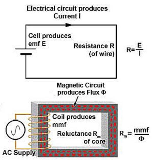
3.4 Read the text, look at the 2 schemes and explain difference between electrical and magnetic circuits.
3.5 Fill in the gaps with following words:
Magnetic circuit analog to electric circuits
|
reluctance current voltage drop magnetomotive force |
The similarities between magnetic circuits and electric circuits are as follows:
1) ___ (1) is equivalent to electromagnetic force;
2) flux is equivalent to ___(2);
3) ___ (3) is equivalent to resistance;
4) magnetic field strength* is equivalent to ___ (4).
|
ampere (A) amperes per weber (A/Wb) magnetomotive force magnetic circuit flux = mmf / reluctance magnetic circuits |
What is the difference between electric and magnetic circuit?
In the general sense, a ___ (5) is any path taken by magnetic flux. More specifically, it is associated with the magnetic flux within (usually) silicon steel 'cores' such as those found in transformer, generators, motors, relays, etc. They can be 'homogenous', where the flux path is completely contained with the same material (e.g. a transformer core), or 'compound', where the flux path incorporates, say, an air gap (e.g. motor/generator fields).
The source of a magnetic circuit's ___ (6) is a current-carrying coil. The magnitude of this mmf is the product of the current flowing through the coil, and the number of turns (I x N). Since the number of turns is dimensionless, the SI unit of measurement of mmf is the ___ (7) although it is frequently 'spoken' of as 'ampere turns', to avoid confusion with the unit for electric current.
Magnetic ___ (8) is measured in webers (Wb), pronounced 'vay-bers'.
Reluctance is measured in ___ (9) although, again, it is frequently spoken as 'ampere-turns per weber'.
Another similarity with electric circuits, is that the equivalent of 'Ohm's Law' also applies to magnetic circuits: i.e. __ (10).
Finally, ___ (11) can also be compared with series, parallel, or series-parallel circuits.
Unit 4
Synchronous machines and winding models
Text 12
Construction of synchronous machines
Like other electrical machines, synchronous machines can be operated as either generators or motors.
In a synchronous generator, a DC current is applied to the rotor winding producing a rotor magnetic field. The rotor is then turned by external means producing a rotating magnetic field, which induces a 3-phase voltage within the stator winding.
1) field windings are the windings producing the main magnetic field (rotor windings).
2) armature windings are the windings where the main voltage is induced (stator windings).
The rotor of a synchronous machine is a large electromagnet. The magnetic poles can be either salient (sticking out of rotor surface) or non-salient construction.
Rotors are made laminated to reduce eddy current losses. Two common approaches are used to supply a DC current to the field circuits on the rotating rotor:
1) supply the DC power from an external DC source to the rotor by means of slip rings and brushes;
2) supply the DC power from a special DC power source mounted directly on the shaft of the machine.
Non-salient-pole rotor: usually two- and four-pole rotors.
Slip rings are metal rings completely encircling the shaft of a machine but insulated from it. Graphite-like carbon brushes connected to DC terminals ride on each slip ring supplying DC voltage to field windings.
1) On large generators and motors, brushless exciters are used.
2) A brushless exciter is a small AC generator whose field circuits are mounted on the stator and armature circuits are mounted on the rotor shaft.
3) The exciter generator’s 3-phase output is rectified to DC by a 3-phase rectifier (mounted on the shaft) and fed into the main DC field circuit.
4) It is possible to adjust the field current on the main machine by controlling the small DC field current of the exciter generator (located on the stator).
A brushless exciter: a low 3-phase current is rectified and used to supply the field circuit of the exciter (located on the stator).
The synchronous generator has two parts:
1) Stator: carries 3 (3-phase) armature windings, AC, physically displaced from each other by 120 degrees.
2) Rotor: carries field windings, connected to an external DC source via slip rings and brushes or to a revolving DC source via a special brushless configuration.
The output of the exciter’s armature circuit (on the rotor) is rectified and used as the field current of the main machine.
To make the excitation of a generator completely independent of any external power source, a small pilot exciter is often added to the circuit. The pilot exciter is an AC generator with a permanent magnet mounted on the rotor shaft and a 3-phase winding on the stator producing the power for the field circuit of the exciter.
By the definition, synchronous generators produce electricity whose frequency is synchronized with the mechanical rotational speed. Where fe is the electrical frequency, Hz; nm is the rotor speed of the machine, rpm; p is the number of poles.
![]()
Steam turbines are most efficient when rotating at high speed; therefore, to generate 60 Hz, they are usually rotating at 3600 rpm (2-pole).
Water turbines are most efficient when rotating at low speeds (200-300 rpm); therefore, they usually turn generators with many poles.
Principles of operation
1. Create a magnetic field on the rotor of an electric machine.
2. Apply an external driving force
3. As the rotor rotates, a voltage is induced in windings on the stator.
4. The frequency of the induced voltage will be synchronized with the speed of rotation.

4.1 Fill in the gaps with following words:
Synchronous machine construction
|
a rotor an armature winding a magnetic field permanent magnets |
A synchronous machine has two mechanical parts: ___ (1) and a stator. There are also two electrical parts to the machine: a field source and ___ (2). These basic fundamentals of an electric machine are like those for a DC machine, with one significant difference: The field source of a synchronous machine is on the rotor, the armature winding of a synchronous machine is on the stator. Like DC machines, the field source creates ___ (3); the armature winding has a voltage induced in it by the field. Also like DC machines, the field can be produced using either a field winding or by using ___ (4). PM (permanent magnet) machines are common in small sizes, whilst large machines are usually made with field windings. (There are some exceptions to this rule, e.g. multi-MW PM motors are being prototyped for ship propulsion):
- The field winding is on the rotor.
- The armature winding is on the stator.
- There is sometimes a damper or armortisseur winding on the rotor.
- The external driving force (e.g. steam or hydro turbine, diesel generator, jet engine) is called the prime mover.
4.2 Match the collocations with Russian equivalents:
a) eddy current losses; slip rings and brushes; graphite-like carbon brushes; mechanical rotational speed; a voltage is induced;
b) механическая скорость вращения; напряжение индуктируется; контактные кольца и щетки; графитоподобные угольные щетки; потери вихревых токов.
4.3 Answer the questions:
1) What is main principle of operation of a synchronous generator?
2) What is a difference between a rotor magnetic field and a rotating magnetic field?
3) What is a difference between field windings and armature windings?
4) What type of the magnetic poles can be in the rotor of a synchronous machine?
5) Why are rotors made laminated?
6) Which are two common approaches used to supply a DC current to the field circuits on the rotating rotor?
7) What are slip rings?
8) What is the function of graphite-like carbon brushes?
9) What is a brushless exciter?
10) What are two parts of the synchronous generator?
11) What is pilot exciter?
12) When are steam turbines most efficient?
13) When are water turbines most efficient?
4.4 Multiple Choice Questions of Synchronous Generator:
1) In an alternator, voltage drops occurs in
a) armature resistance only.
b) armature resistance and leakage reactance.
c) armature resistance, leakage reactance and armature reaction.
d) armature resistance, leakage reactance, armature reaction and earth connections.
2) The magnitude of various voltage drops that occur in an alternator, depends on
a) power factor of the load
b) load current
c) power factor x load current
d) power factor x (load current)
3) In an alternator, at lagging power factor, the generated voltage per phase, as compared to that at unity power factor
a) must be same as terminal voltage
b) must be less than the terminal voltage
c) must be more than the terminal voltage
d) must be 1.41 time the terminal voltage
4) The power factor of an alternator depends on
a) load
b) speed of rotor
c) core losses
d) armature losses
5) Which kind of rotor is most suitable for turbo alternators which are designed to run at high speed?
a) Salient pole type
b) Non-salient pole type
c) Both (A) and (B) above
d) None of the above
6) Salient poles are generally used on
a) high speed prime movers only
b) medium speed prime movers only
c) low speed prime movers only
d) low and medium speed prime movers
7) The frequency of voltage generated in an alternator depends on
a) number of poles
b) rotative speed
c) number of poles and rotative speed
d) number of poles, rotative speed and type of winding
8) The frequency of voltage generated by an alternator having 8 poles and rotating at 250 rpm is
a) 60 Hz
b) 50 Hz
c) 25 Hz
d) 16 2/3 Hz
9) An alternator is generating power at 210 V per phase while running at 1500 rpm. If the need of the alternator drops to 1000 rpm, the generated voltage per phase will be
a) 180 V
b) 150 V
c) 140 V
d) 105 V
10) A 10 pole AC generator rotates at 1200 rpm. The frequency of AC voltage in cycles per second will be
a)120
b) 110
c) 100
d) 50
11) The number of electrical degrees passed through in one revolution of a six pole synchronous alternator is
a) 360
b) 720
c) 1080
d) 2160
12) Fleming's left hand rule may be applied to an electric generator to find out
a) direction of rotor rotation
b) polarity of induced emf
c) direction of induced emf
d) direction of magnetic field
13) If the input to the prime mover of an alternator is kept constant but the excitation is changed, then the
a) reactive component of the output is changed
b) active component of the output is changed
c) power factor of the load remains constant
d) power factor of the load reduces
14) An alternator is said to be over excited when it is operating at
a) unity power factor
b) leading power factor
c) lagging power factor
d) lagging to leading power factor.
15) When an alternator is running on no load the power supplied by the prime mover is mainly consumed
a) to meet iron losses
b) to meet copper losses
c) to meet all no load losses
d) to produce induced emf in armature winding
4.5 Fill in the gaps with following words:
The difference between Asynchronous and synchronous generator and advantages of both
|
frequency constant value stator windings permanent magnets battery power level electronic controllers electromagnetic induction rotation |
A synchronous generator is called “synchronous” because the waveform of the generated voltage is synchronized with the ___ (1) of the generator. Each peak of the sinusoidal waveform corresponds to a physical position of the rotor. The ___ (2) is exactly determined by the formula f = RPM x p / 120 where f is the frequency (Hz), RPM is the rotor speed (revolutions per minute) and p is the number of poles formed by the ___ (3). A synchronous generator is essentially the same machine as a synchronous motor. The magnetic field of the rotor is supplied by direct current or ___ (4).
The output frequency of an asynchronous generator is slightly (usually about 2 or 3%) lower than the frequency calculated from f = RPM x p / 120. If the RPM is held constant, the frequency varies depending on the ___ (5). The peaks of the waveform have no fixed relationship with the rotor position. An asynchronous generator is essentially the same machine as an asynchronous or induction motor. The magnetic field of the rotor is supplied by the stator through ___ (6).
The output frequency of a synchronous generator can be more easily regulated to remain at a ___ (7). Synchronous generators (large ones at least) are more efficient than asynchronous generators. Synchronous generators can more easily accommodate load power factor variations. Synchronous generators can be started by supplying the rotor field excitation from a ___ (8). Permanent magnet synchronous generators require no rotor field excitation.
The construction of asynchronous generators is less complicated than the construction of synchronous generators. Asynchronous generators require no brushes and thus no brush maintenance. Asynchronous generators require relatively complicated ___ (9). They are usually not started without an energized connection to an electric power grid, unless they are designed to work with a battery bank energy storage system. With an asynchronous generator and an electronic controller, the speed of the generator can be allowed to vary with the speed of the wind. The cost and performance of such a system is generally more attractive than the alternative systems using a synchronous generator.
Text 13
Synchronous motors
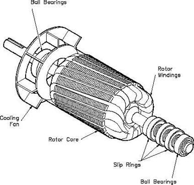
Synchronous motors are inherently constant-speed motors and they operate in absolute synchronism with line frequency. Hansen offers both Hysteresis and Permanent Magnet synchronous motors (PM Synchronous Motors) to meet your exact needs. The hysteresis design, Hansen's famous Genuine Synchron®, is extremely quiet and smooth in operation and has very low cogging torque, ideal for back-driving. Because it is light in torque, it is always attached to a Hansen ultra precision gearbox. The permanent magnet motor design offers higher torque and is available with or without a gearbox. The high strength magnets create substantial cogging torque, making these synchronous motors ideal for applications where you need to hold position after removing power.
As with squirrel-cage induction motors, speed is determined by the number of pairs of poles and is always a ratio of the line frequency.
Synchronous motors are made in sizes ranging from sub fractional self-excited units to large-horsepower, direct-current-excited motors for industrial drives. In the fractional-horsepower range, synchronous motors are used primarily where precise constant speed is required.
In large horsepower sizes applied to industrial loads, synchronous motors serve two important functions. First, it is a highly efficient means of converting ac energy to mechanical power. Second, it can operate at leading or unity power factor, thereby providing power-factor correction.
There are two major types of synchronous motor: nonexcited and direct-current excited.
Nonexcited Synchronous motors are made in reluctance and hysteresis designs. These motors employ a self-starting circuit and require no external excitation supply.
Dc-excited Synchronous motors come in sizes larger than 1 hp, and require direct current supplied through slip rings for excitation. Direct current may be supplied from a separate source or from a dc generator directly connected to the motor shaft.
Single-phase or polyphase synchronous motors can't start without being driven, or having their rotor connected in the form of a self-starting circuit. Since the field is rotating at synchronous speed, the motor must be accelerated before it can pull into synchronism. Acceleration from zero speed requires slip until synchronism is reached. Therefore, separate starting means must be employed.
In self-starting designs, fhp sizes use starting methods common to induction motors (split-phase, capacitor-start, repulsion-start, and shaded-pole). The electrical characteristics of these motors cause them to automatically switch to synchronous operation.
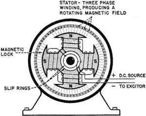
Although the dc-excited motor has a squirrel cage for starting, called an amortisseur or damper winding, the inherent low starting torque and the need for a dc power source requires a starting system that provides full motor protection while starting, applies dc field excitation at the proper time, removes field excitation at rotor pull out (maximum torque), and protects the squirrel-cage winding against thermal damage under out-of-step conditions.
Pull-up torque is the minimum torque developed from standstill to the pull-in point. This torque must exceed load torque by a sufficient margin so that a satisfactory rate of acceleration is maintained under normal voltage conditions.
Reluctance torque results from the saliency (preferred direction of magnetization) of the rotor pole pieces and pulsates at speeds below synchronous. It also has an influence on motor pull-in and pull-out torques because the unexcited salient-pole rotor tends to align itself with the stator magnetic field to maintain minimum magnetic reluctance. This reluctance torque may be sufficient to pull into synchronism a lightly loaded, low-inertia system and to develop approximately a 30% pull-out torque.
Synchronous torque is torque developed after excitation is applied, and represents the total steady-state torque available to drive the load. It reaches maximum at approximately 70° lag of the rotor behind the rotating stator magnetic field. This maximum value is actually the pull-out torque.
Pull-out torque is the maximum sustained torque the motor develops at synchronous speed for one minute with rated frequency and normal excitation. Normal pull-out torque is usually 150% of full-load torque for unity-power-factor motors, and 175 to 200% for 0.8-leading-power-factor motors.
Pull-in torque of a synchronous motor is the torque that it develops when pulling its connected inertia load into synchronism upon application of excitation. Pull-in torque is developed during transition from slip speed to synchronous speed, as the motor changes from induction to synchronous operation. It is usually the most critical period in starting a synchronous motor. Torques developed by the amortisseur and field windings become zero at synchronous speed. At the pull-in point, therefore, only the reluctance torque and the synchronizing torque provided by exciting the field windings are effective.
4.6 Match the collocations with Russian equivalents:
a) synchronous motors; constant-speed motors; line frequency; torque; cogging; gearbox; removing power; squirrel-cage induction motors; industrial drive; power-factor correction; reluctance; motor shaft;
b) коррекция коэффициента мощности индукционные двигатели с короткозамкнутым ротором вращающийся момент; вал двигателя; отключение питания; промышленный привод; магнитное сопротивление; коробка передач; двигатели с постоянной частотой вращения; частота сети; cинхронные двигатели; зубчатый.
4.7 Answer the questions:
1) What are synchronous motors?
2) What are the main characteristics of the hysteresis design?
3) How is speed determined?
4) In which sizes are synchronous motors made?
5) What are two important functions synchronous motors serve?
6) What are two major types of synchronous motor?
7) Can single-phase or polyphase synchronous motors start without being driven? Why?
8) Does in self-starting designs, fhp sizes use starting methods differ from induction motors?
9) What does a starting system require?
10) Why must the torque exceed load torque by a sufficient margin?
11) What is pull-up torque?
12) What is synchronous torque?
13) What is pull-out torque?
14) What is pull-in torque?
4.8 Multiple Choice Questions of Synchronous Motors:
1) Synchronous motor can operate at
a) lagging power factor only.
b) leading power factor only.
c) unity power factor only.
d) lagging, leading and unity power factor only.
2) An unexcited single phase synchronous motor is
a) reluctance motor.
b) repulsion motor.
c) universal motor.
d) AC series motor.
3) The maximum power developed in the synchronous motor will depend on
a) rotor excitation only.
b) maximum value of coupling angle.
c) supply voltage only.
d) rotor excitation supply voltage and maximum value of coupling angle.
4) In case the field of a synchronous motor is under excited, the power factor will be
a) leading.
b) lagging.
c) zero.
d) unity.
5) A synchronous motor is switched on to supply with its field windings shorted on themselves. It will
a) not start.
b) start and continue to run as an induction motor.
c) start as an induction motor and then run as synchronous motor.
d) bum immediately.
6) When the excitation of an unloaded salient pole synchronous motor gets disconnected
a) the motor will bum.
b) the motor will stop.
c) the motor will ran as a reluctance motor at the same speed.
d) the motor will run as a reluctance motor at a lower speed.
7) The damping winding in a synchronous motor is generally used
a) to provide starting torque only.
b) to reduce noise level.
c) to reduce eddy currents.
d) to prevent hunting and provide the starting torque.
8) The back emf set up in the stator of a synchronous motor will depend on
a) rotor speed only.
b) rotor excitation only.
c) rotor excitation and rotor speed.
d) coupling angle, rotor speed and excitation.
9) A synchronous motor is a useful industrial machine on account of which of the following reasons?
I. It improves the power factor of the complete installation
II. Its speed is constant at all loads, provided mains frequency remains constant
III. It can always be adjusted to operate at unity power factor for optimum efficiency and economy.
a) I only.
b) II only.
c) III only.
d) I, II and III.
10) Which of the following is an unexcited single phase synchronous motor?
a) A.C. series motor.
b) Universal motor.
c) Reluctance motor.
d) Repulsion motor.
11) An over excited synchronous motor draws current at
a) lagging power factor.
b) leading power factor.
c) unity power factor.
d) depends on the nature of load.
12) With the increase in the excitation current of synchronous motor the power factor of the motor will
a) improve.
b) decrease.
c) remain constant.
d) depend on other factors.
13) The armature current of a synchronous motor has large values for
a) low excitation only.
b) high excitation only.
c) both low and high excitation.
d) depends on other factors.
14) A synchronous motor is switched on to supply with its field windings shorted on themselves. It will
a) not start.
b) start and continue to run as an induction motor.
c) start as induction motor and then run as a synchronous motor.
15) If the field of a synchronous motor is under excited, the power factor will be
a) lagging.
b) leading.
c) unity.
Unit 5
Smart Energy
Text 14
Smart Energy
)
The next few decades will see great changes in the way energy is supplied and used. In some major oil producing nations, 'peak oil' has already been reached, and there are increasing fears of global warming. Consequently, many countries are focusing on the switch to a low carbon economy. This transition will lead to major changes in the supply and use of electricity. [A] Firstly, there will be an increase in overall demand, as consumers switch from oil and gas to electricity to power their homes and vehicles. [B] Secondly, there will be an increase in power generation, not only in terms of how much is generated, but also how it is generated, as there is growing electricity generation from renewable sources. [C] To meet these challenges, countries are investing in Smart Grid technology. [D] This system aims to provide the electricity industry with a better understanding of power generation and demand, and to use this information to create a more efficient power network.
Smart Grid technology basically involves the application of a computer system to the electricity network. The computer system can be used to collect information about supply and demand and improve engineer's ability to manage the system. With better information about electricity demand, the network will be able to increase the amount of electricity delivered per unit generated, leading to potential reductions in fuel needs and carbon emissions. Moreover, the computer system will assist in reducing operational and maintenance costs.
Smart Grid technology offers benefits to the consumer too. They will be able to collect real-time information on their energy use for each appliance. Varying tariffs throughout the day will give customers the incentive to use appliances at times when supply greatly exceeds demand, leading to great reductions in bills. For example, they may use their washing machines at night. Smart meters can also be connected to the internet or telephone system, allowing customers to switch appliances on or off remotely. Furthermore, if houses are fitted with the apparatus to generate their own power, appliances can be set to run directly from the on-site power source, and any excess can be sold to the grid.
With these changes comes a range of challenges. The first involves managing the supply and demand. Sources of renewable energy, such as wind, wave and solar, are notoriously unpredictable, and nuclear power, which is also set to increase as nations switch to alternative energy sources, is inflexible. With oil and gas, it is relatively simple to increase the supply of energy to match the increasing demand during peak times of the day or year. With alternative sources, this is far more difficult, and may lead to blackouts or system collapse. Potential solutions include investigating new and efficient ways to store energy and encouraging consumers to use electricity at off-peak times.
A second problem is the fact that many renewable power generation sources are located in remote areas, such as windy uplands and coastal regions, where there is currently a lack of electrical infrastructure. New infrastructures therefore must be built. Thankfully, with improved smart technology, this can be done more efficiently by reducing the reinforcement or construction costs.
Although Smart Technology is still in its infancy, pilot schemes to promote and test it are already underway. Consumers are currently testing the new smart meters which can be used in their homes to manage electricity use. There are also a number of demonstrations being planned to show how the smart technology could practically work, and trials are in place to test the new electrical infrastructure. It is likely that technology will be added in 'layers', starting with 'quick win' methods which will provide initial carbon savings, to be followed by more advanced systems at a later date. Cities are prime candidates for investment into smart energy, due to the high population density and high energy use. It is here where Smart Technology is likely to be promoted first, utilizing a range of sustainable power sources, transport solutions and an infrastructure for charging electrically powered vehicles. The infrastructure is already changing fast. By the year 2050, changes in the energy supply will have transformed our homes, our roads and our behaviour.Начало формы
1 According to paragraph 1, what has happened in some oil producing countries?
a) They are unwilling to sell their oil any more.
b) They are not producing as much oil as they used to.
c) The supply of oil is unpredictable.
d) Global warming is more sever here than in other countries.
2 Where in paragraph 1 can the following sentence be placed?
There are also likely more electricity generation centers, as households and communities take up the opportunity to install photovoltaic cells and small scale wind turbines.
a)
b)
c)
d)
3 Which of the following is NOT a benefit of Smart Grid technology to consumers?
a) It can reduce their electricity bills.
b) It can tell them how much energy each appliance is using.
c) It can allow them to turn appliances on and off when they are not at home.
d) It can reduce the amount of energy needed to power appliances.
4 According to paragraph 4, what is the problem with using renewable sources of power?
a) They do not provide much energy.
b) They often cause system failure and blackouts.
c) They do not supply a continuous flow of energy.
d) They can't be used at off-peak times.
5 In paragraph 5, what can be inferred about cities in the future?
a) More people will be living in cities in the future than nowadays.
b) People in cities will be using cars and buses powered by electricity.
c) All buildings will generate their own electricity.
d) Smart Grid technology will only be available in cities.
6 The word 'remote' in paragraph 5 could be best replace by:
a) isolated.
b) crowded.
c) attractive.
d) alone.
7 The word 'underway' in paragraph 6 is closest in meaning to:
a) permanent.
b) complete.
c) beneficial.
d) in progress.
8 What is the main idea of the final paragraph? (paragraph 6).
a) To describe who will benefit from Smart Grid technology first.
b) To outline the advantages of Smart Grid technology.
c) To summarize the main ideas in the previous paragraphs.
d) To describe how, where and when Smart Technology will be introduced.
9 In paragraph 6, what can be inferred about the introduction of Smart Grid Technology?
a) The technologies which produce most benefits will be introduced first.
b) The cheapest technologies will be introduced first.
c) The technologies which are most difficult to put into place will be introduced first.
d) Technologically advanced systems will be introduced first.
10-12 Which three of the aspects below are answered in the passage?
a) How
consumers are likely to respond to Smart Grid technology.![]()
b) The problems which will have to be overcome in switching to Smart Grid technology.
c) The
reasons why Smart Grid technology will be needed in the future.![]()
d) A comparison between Smart Grid technology and the present electrical distribution system.
e) The
ways Smart Grid technology will affect the way consumers use energy.![]()
f) An analysis of the costs and benefits of Smart Grid technology.
Keys:
Unit 2
Polуphase power system
2.3 Answer the questions:
1) A "balanced" polyphase system is one where all line voltages are equal to each other, and all line currents are also equal to each other. Unbalanced" conditions usually stem from unsymmetrical loads, although severe imbalances may be caused by faults in the system.
2) In polyphase systems, there are multiple voltages phase-shifted apart from each other so as to be intentionally out of step." Although the rationale for polyphase electrical power may not be apparent from either the question or the given answer, your students need to be aware of its existence.
3) Generating and distributing AC power in three-phase form is more efficient than if it were done in single-phase form. Please do not accept the given answer as a student response! This answer is very shallow, not communicating much meaning. Ask your students to explain why polyphase power systems enjoy greater efficiencies than monophase power systems. There is more than one correct answer to this question!
4) Polyphase AC voltages are usually created by special alternators, with different "phase" windings spaced around the circumference of the stator. An illustration of polyphase alternator construction would be excellent to aid understanding of this concept. Your students should have no trouble finding illustrations of three-phase alternator design from textbooks and from the internet.
5) The lamps will blink from left to right (C-B-A-C-B-A). Follow-up question: suppose lamp B stopped blinking, while lamps A and C continued. Identify at least two possible causes for this failure. This question is really a prelude to discussing phase rotation in polyphase systems.
6) "Phase rotation sequence" refers to the successive order in which the various phase voltages reach their positive peaks. Ask your students how the phase rotation sequence of a three-phase system is typically denoted. What symbols are used to describe the direction in which the phase voltages "rotate"?
7) Phase voltage = 277 volts AC (given) Line voltage = VAB = VBC = VAC = 480 volts AC.

Follow-up question #1: what is the ratio between the line and phase voltage magnitudes in a Y-connected three-phase system? Follow-up question #2: what would happen to the output of this alternator if the rotor winding were to fail open? Bear in mind that the rotor winding is typically energized with DC through a pair of brushes and slip rings from an external source, the current through this winding being used to control voltage output of the alternator's three-phase ßtator" windings.
Students will quickly discover that √3 is the "magic number" for practically all balanced three-phase circuit calculations! It should be noted that although the magnitudes of VAB, VBC, and VAC are equal, their phasor angles are most definitely not.
|
||
|
8) Phase current = 17 amps AC (given)
Line current = IA = IB = IC = 29.4 amps AC
Follow-up question #1: what is the ratio between the line and phase current magnitudes in a Delta-connected three-phase system?
Follow-up question #2: what would happen to the output of this alternator if the rotor winding were to fail open? Bear in mind that the rotor winding is typically energized with DC through a pair of brushes and slip rings from an external source, the current through this winding being used to control voltage output of the alternator's three-phase ßtator" windings. Students will quickly discover that √3 is the "magic number" for practically all balanced three-phase circuit calculations! It should be noted that although the magnitudes of IA, IB, and IC are equal, their phasor angles are most definitely not. Therefore,
|
|
|
9)
Many students are confused by this when seeing it for the first time. How is it possible to measure voltage between two points in a circuit and obtain 208 volts, when the two series-connected voltage sources between those two points are 120 volts each? Why isn't it 240/120 volts instead?
The answer to this question, of course, is phase shift: the answer to most ßtrange" phenomenon in AC circuits!
10) On a single-phase system, there should be no change in light bulb brightness as the switch is opened and closed. On a three-phase system, there will be a change in brightness between the two different switch states (I'll let you figure out which switch state makes the light bulbs glow brighter!). The subject of this question is closely related to the subject of ßingle-phasing" a polyphase load as the result of a line conductor opening. In this case it is the neutral conductor we are intentionally opening, but the results are similar.
11) VAB = VBC = VAC = 240 volts,
VAG = VCG = 120 volts,
VBG = 208 volts.
Despite the fact that this connection scheme is quite common in industry, I have found little reference to it in textbooks. The equilateral layout of the windings in this diagram facilitates graphical (phasor) analysis of the voltages, providing students with the opportunity to exercise their knowledge of trigonometry.
12) Ptotal = 27.648 kW,
Iline = 33.255 A.
I'll let you derive your own equation for power calculation. Be ready to show your work!
Now, students will surely be able to find a power equation from textbooks, but the purpose of this question is to have them derive it themselves. In a single-phase, resistive AC circuit, power is given by the equation P = I E, just as in DC circuits. However, if you multiply the line voltage by line current, you do not get the correct answer of 27.648 kW. So, obviously, the equation of P = I E will require some modification for calculating total three-phase power. However, this modification is not complicated to perform.
13) Pload = 3.59 MW.
A single-phase system operating at 13.8 kV would require at least 1/0 (öne-ought") gauge copper conductors to transmit 3.59 MW of power. A three-phase system operating at the same voltage would require at least #2 gauge copper conductors.
This question is good for provoking discussion on the practical, cost-saving benefits of three-phase power systems over single-phase. Your students will have to do some "review" research on wire gauges and weights, but the exercise is well worth it.
14) Iline = 160.81 amps.
Several conversions are necessary to calculate the answer for this question. As usual, the purpose of this question is not so much to obtain an answer, as it is to develop students' problem-solving skills. How did students approach this problem? Did any of them think of ways to simplify the problem so that it could be solved in incremental steps instead of all at once? If so, what was their method(s) of solution?
Text 9
2.7 Answer the questions:
1)
Y configuration
Iphase = Iline;
Vphase < Vline.
Delta configuration
Vphase = Vline;
Iphase < Iline.
Follow-up question: how do Kirchhoff's Voltage and Current Laws explain the relationships between unequal quantities in "Y" and "Delta" configurations?
Your students will need to know what "phase" and "line" represents in both types of polyphase configurations, especially when using formulae that reference quantities by these labels.
2) A "balanced" polyphase system is one where all line voltages are equal to each other, and all line currents are also equal to each other. Ünbalanced" conditions usually stem from unsymmetrical loads, although severe imbalances may be caused by faults in the system. Ask your students which type of three-phase system (balanced or unbalanced) is easier to analyze, and why that is so.
3) Ephase = 277 V.
More important than obtaining the correct answer is for students to explain what they did to get that answer. What general calculation may be applied to balanced, Y-connected systems relating phase and line voltages?
4) Eline = 230 V,
Iline = 7.967 A,
Ephase(source) = 230 V,
Iphase(source) = 4.6 A,
Ephase(load) = 230 V,
Iphase(load) = 4.6 A,
Ptotal = 3.174 kW.
Be sure to ask your students to describe how they arrived at the answers to this question. There is more than one place to start in determining the solution here, and more than one way to calculate some of the figures. No matter how your students may have approached this question, though, they should all obtain the same answers.
5) Eline = 13.8 kV,
Iline = 5.312 A,
Ephase(source) = 7.967 kV,
Iphase(source) = 5.312 A,
Ephase(load) = 7.967 kV,
Iphase(load) = 5.312 A,
Ptotal = 126.96 kW.
Be sure to ask your students to describe how they arrived at the answers to this question. There is more than one place to start in determining the solution here, and more than one way to calculate some of the figures. No matter how your students may have approached this question, though, they should all obtain the same answers.
6) Eline = 2400 V,
Iline = 4.619 A,
Ephase(source) = 2400 V,
Iphase(source) = 2.667 A,
Ephase(load) = 1385.6 V,
Iphase(load) = 4.619 A,
Ptotal = 19.2 kW.
Be sure to ask your students to describe how they arrived at the answers to this question. There is more than one place to start in determining the solution here, and more than one way to calculate some of the figures. No matter how your students may have approached this question, though, they should all obtain the same answers.
7) Eline = 207.8 V,
Iline = 0.621 A,
Ephase(source) = 120 V,
Iphase(source) = 0.621 A,
Ephase(load) = 207.8 V,
Iphase(load) = 0.358 A,
Ptotal = 223.4 W.
Be sure to ask your students to describe how they arrived at the answers to this question. There is more than one place to start in determining the solution here, and more than one way to calculate some of the figures. No matter how your students may have approached this question, though, they should all obtain the same answers.
8) Each resistor in a Delta-connected network must have a value of 900 Ω, to be equivalent to a Y-connected network of 300 Ω resistors.
There exist long, complicated equations for converting between Y and Delta resistor networks, but there is a much simpler solution to this problem than that! Challenge your students to solve this problem without resorting to the use of one of those long conversion formulae.
9) In the Y-Y system, with no neutral wire, one of the load phases will completely lose power, while the voltages of the other two load phases will be reduced to 86.7 % of normal. In the Delta-Y system, none of the phase voltages will be affected by the failure of the source phase winding.
Ask your students what these results indicate about the reliability of Y versus Delta source configurations. Also, be sure to ask whatdoes change in the Delta-Y system as a result of the failure. Certainly, something must be different from before, with one winding completely failed open!
10)
VAB = 240 volts, VBC = 240 volts,
VAC = 240 volts,
VAN =
120 volts,
VBN = 208 volts, VCN = 120 volts.
The usefulness of this connection scheme should be clearly evident: three different voltage levels may be accessed for use in powering circuits. Usually, the coils shown are secondary windings of three different transformers, the primary windings connected to a set of three-phase high voltage power lines. In many cases, a heavier-duty transformer is used for coil AC than for coils AB or BC due to the number of 120 volt loads.
11) Delta-Y.
Three-phase power transformers are somewhat rare compared to combinations of multiple single-phase transformers. Questions such as this are really nothing more than pattern-recognition exercises, but like all skills this does not come naturally to all people, and practice improves it!
12)
Of course, this is not the only way these three transformers could be connected in a Y-Y configuration.
Being that pole-mounted power distribution transformers are exposed for anyone to look at, they provide an excellent opportunity for students to practice identifying three-phase connections. If there are any such transformer configurations located near your campus, it would be an interesting field exercise to bring students there (or send them there on "field research"!) to identify the connections. Photographs of transformer connections may also be used in the classroom to provide practical examples of this concept.
13) These transformers are connected in a Y-Delta configuration.
Being that pole-mounted power distribution transformers are exposed for anyone to look at, they provide an excellent opportunity for students to practice identifying three-phase connections. If there are any such transformer configurations located near your campus, it would be an interesting field exercise to bring students there (or send them there on "field research"!) to identify the connections. Photographs of transformer connections may also be used in the classroom to provide practical examples of this concept.
14) These transformers are connected in an open-Delta configuration.
Understanding the open-Delta configuration is made easier if students first understand the robustness of the regular Delta configuration: how it continues to provide true three-phase power with no degradation in line voltage in the event of a winding failure. Discuss the advantages and disadvantages of such a configuration with your students.
15) Here's a hint: if you were to repair the neutral wire and take current measurements with a digital instrument (using a clamp-on current probe, for safety), you would find that the predominant frequency of the current is 180 Hz, rather than 60 Hz.
This scenario is all too common in modern power systems, as non-linear loads such as switching power supplies and electronic power controls become more prevalent. Special instruments exist to measure harmonics in power systems, but a simple DMM (digital multimeter) may be used as well to make crude assessments such as the one described in the Answer.
Unit 3
Magnetic circuit analog to electric circuits
3.5 Fill in the gaps with following words:
1) magnetomotive force
2) current
3) reluctance
4) voltage drop
5) magnetic circuit
6) magnetomotive force
7) ampere (A)
8) flux
9) amperes per weber (A/Wb)
10) flux = mmf / reluctance
11) magnetic circuits
Unit 4
Synchronous machines and winding models
4.4 Multiple Choice Questions of Synchronous Generator:
1) C
2) B
3) C
4) A
5) B
6) D
7) C
8) D
9) C
10) C
11) C
12) C
13) A
14) C
15) C
4.5 The difference between Asynchronous and synchronous generator and advantages of both
1) rotation
2) frequency
3) stator windings
4) permanent magnets
5) power level
6) electromagnetic induction.
7) constant value
8) battery
9) electronic controllers
4.8 Multiple Choice Questions of Synchronous Motors:
1) D
2) A
3) D
4) B
5) C
6) B
7) D
8) B
9) D
10) C
11) B
12) A
13) C
14) C
15) A
Unit 5
Smart Energy
1) B
2) C
3) D
4) C
5) B
6)A
7) D
8) D
9) A
10-12) B, C, E
Literature
1. http://www.vanrijnelectric.com/vanrijnelectricpowerfactorcorrection.htm
2. http://www.allaboutcircuits.com/vol_2/chpt_11/1.html
3. http://ptuece.loremate.com/mct/node/2
4. http://www.electricalquizzes.com/Synchronous_Generator/Synchronous_Generator_Theory_2.htm
Сводный план 2013г., поз. 223
Луара Дмитриевна Сергеева
АНГЛИЙСКИЙ ЯЗЫК
(профессиональный)
Методические указания для магистрантов по специальности
6М071800 - Электроэнергетика
Редактор А.Т. Сластихина
Специалист по
стандартизации Н.Қ. Молдабекова
Подписано в
печать___________
Формат 60х84 1/16
Бумага типографская № 1
Тираж 50 экз.
Объем 4,1 уч. –
изд. л.
Заказ______. Цена 2050
тг.
Копировально-множительное
бюро
Некоммерческого акционерного общества
«Алматинский университет энергетики и связи»
050013, Алматы, Байтурсынова, 126.